Ansi Weld Symbols Explained

Stick Welding Projects Welding Types Of Welding Welding Projects Welding

Welding Positions Aws Google Search Soldadura Arte De Soldadura Taller De Soldadura Y Soldadura Tig

Stick Welding Projects Welding Types Of Welding Welding Projects Welding

Feature Control Frame Technical Drawing Mechanical Engineering Design Drawings
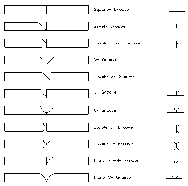
Groove Welding Symbols Interpretation Of Metal Fab Drawings

Gd T Symbols Reference Guide From Sigmetrix Engineering Symbols Mechanical Design Mechanical Engineering Design
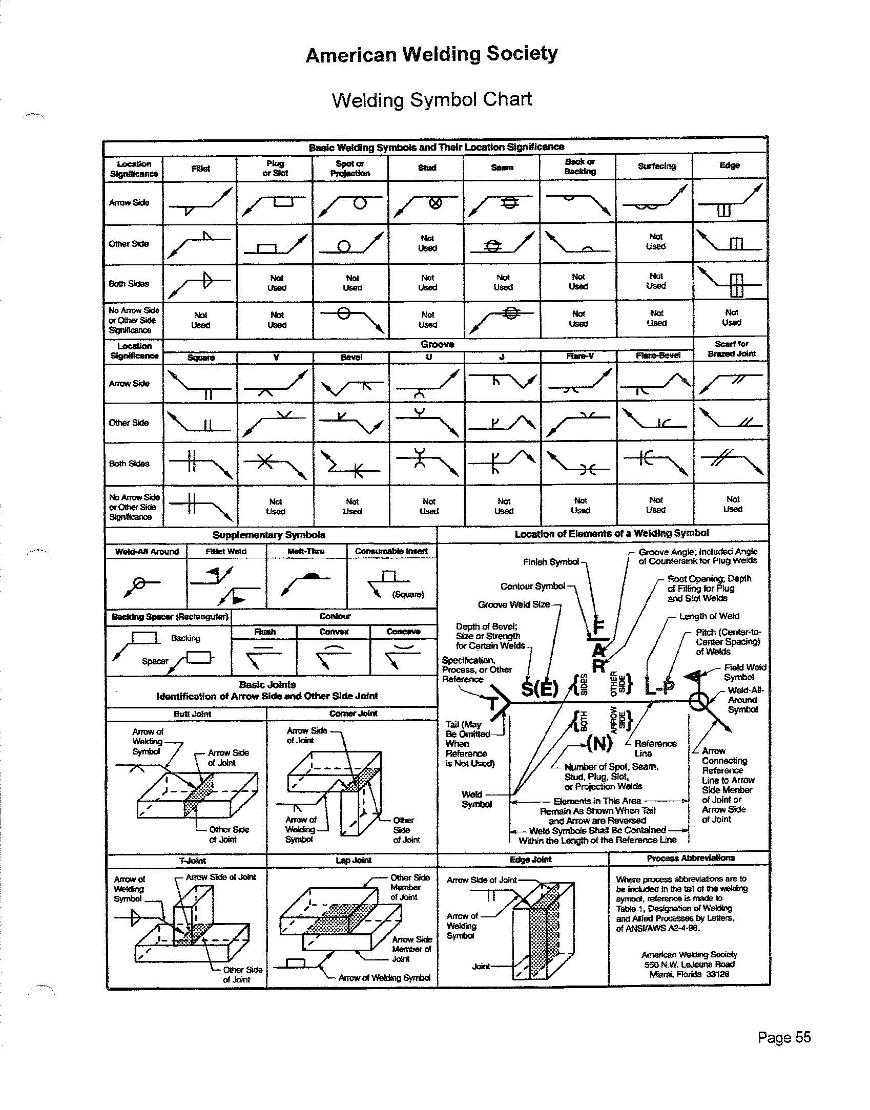
The assembled welding symbol consists of the following eight elements or any of these elements as necessary.
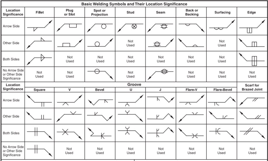
Ansi weld symbols explained. When the symbol is centered on the reference line this indicates that there is no side significance. The weld symbol fig. 3 2 is a method of representing the weld symbol on drawings. The complete set of symbols is given in a standard published by the american national standards institute ansi and the american welding society aws.
When the weld symbol hangs below the reference line it indicates that the weld must be performed on the arrow side of the joint. The structure of the welding symbol. It contains all the necessary information viz. The welding symbol fig.
This placement is important. The three weld symbols you see in the drawings above represent a square fillet and v groove weld respectively. A basic weld symbol consists of three parts namely. Welding symbols are a set of information conveyed by the design department to the welding engineer and the welding operator.
Ansi aws a2 4 symbols for welding and nondestructive testing. Welding position dimensions and geometry of the weld details of groove fillet welding process etc. A distinction is made between the terms weld symbol and welding symbol. For example in the next drawing a fillet weld is specified on the arrow side.
Advanced welding symbols 151 field weld a field weld is defined by the american welding society aws as a weld made at a location other than a shop or the place of initial construction 1 the field weld symbol consists of a flag that is placed at the intersection where the end of the reference line meets the arrow see figure 10 5. 3 3 indicates the desired type of weld.

Complete Welding Symbol Explained Weld Joints And Welding Symbols Part 3 Youtube

Mis Understanding Welding Symbols Part 1 American Welding Society Education Online
Welding Symbols Edge To Edge Guide Makers Legacy

Mechanical Engineering Common Joint Types Mechanical Engineering Design Mechanical Engineering Mechanic
Direction Of The Field Weld Symbol

Modern Welding 11th Edition Page 57 57 Of 896
Slot Plug Weld Symbols Weld Guru

In Order To Analyze The Second Condition For A Flow Process Chart One Should Use The Ansi Standard Symbols The Ansi Stan Process Map Process Chart Flow Chart
Http Www Ritalka Com Secured Docs Ritalka 20training 20tab Welding Welding 20topic 20understanding 20groove 20weld 20symbols Pdf

A Family Of Graphic Symbols Has Been Developed To Represent Fluid Power Components And Systems On Schematic Hydraulic Systems Schematic Drawing Hydraulic Fluid

Pin On Orfs Hydraulic Fittings Adapter Drawing Size Chart

Symbols And Conventions Used In Welding Documentation Wikipedia

Chapter 4 Iso Symbols Other Technologies Content From Hydraulics Pneumatics Neumatica Instalacion Hidraulica Neumaticos

