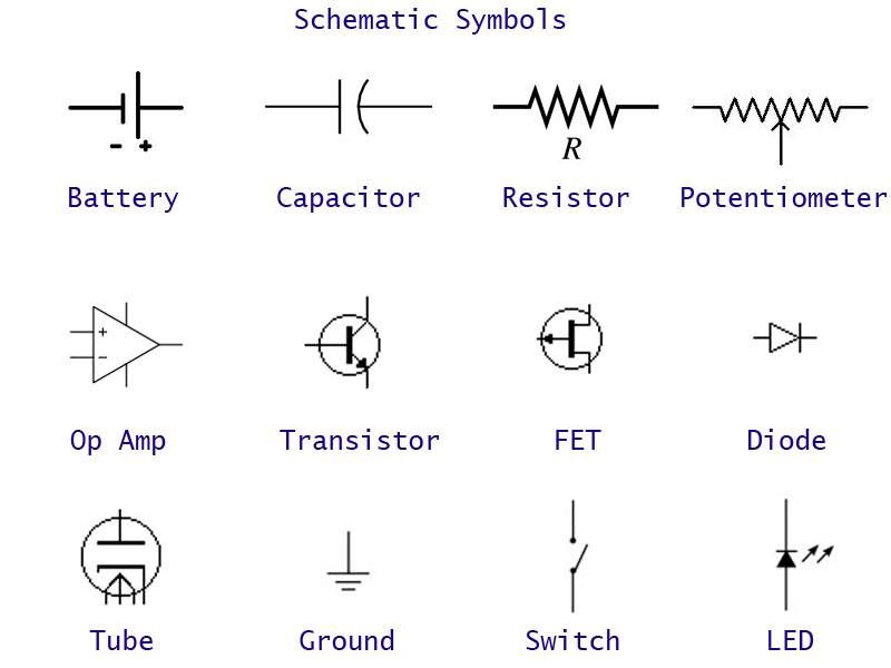
Earth Ground Schematic Symbol

To identify a noiseless clean earth ground terminal e g.
Earth ground schematic symbol. In electrical engineering ground or earth is the reference point in an electrical circuit from which voltages are measured a common return path for electric current or a direct physical connection to the earth. Digital common ground. Even if there is no earth or chassis connection it is common to refer to one point or voltage in the circuit as ground. To identify an earth ground terminal in cases where neither the symbol 5018 nor 5019 is explicitly stated.
Even us electrical codes are sloppy with the symbols. Connected to the chassis of the circuit. Usually in electronics ground is just a name we give to a certain point in the circuit. The standards clearly call out the ground symbol as meaning earth ground the general part does not mean its wise to use it for any random circuit reference it means it represents earth ground when there is not a more specific earth ground symbol that applies.
Of a specially designed earthing grounding system to avoid causing malfunction of the equipment. However ground as a concept can be confusing as it relates to three different situations. 5018 noiseless clean earth ground. The ground symbol keeps appearing at different points in a circuit and i could not understand why a particular place was chosen for grounding and here is what i wrote back.
Electrical circuits may be connected to ground earth for several reasons. Electrical ground symbols of circuit diagram earth ground chassis ground digital ground. To identify an earth ground terminal in cases where neither the symbol 5018 nor 5019 is explicitly stated. In a circuit with one battery with a positive and a negative terminal we.
Electrical equipment may be designed with a floating ground for one of several reasons. Chassis ground for a device signal ground for very low voltage signals within a device and earth ground for a power system. 5018 noiseless clean earth ground. The ground symbols indicate the generic reference point.
It also eliminates some wiring and un clutters the schematic. Here are the precise iec definitions for each symbol. Graphical symbols for use on equipment figure 1. Used for zero potential reference and electrical shock protection.
Ground or gnd use of the ground symbol gives instant visualisation of the grounded points on the circuit. All three indicate connecting to a point of theoretically zero voltage but within a different context. For example a low voltage dc power supply such as a mobile phone charger is connected to the mains through a transformer of one type or another and there is no direct electrical connection between the current return path on the low voltage side and physical ground earth.


