Electrical Moisture Sensor Circuit Symbol

Photoelectric sensors symbols for use in electrical pneumatic and hydraulic schematic diagrams.
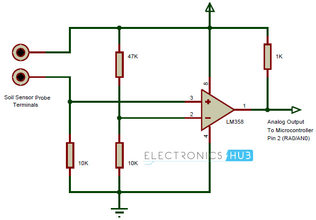
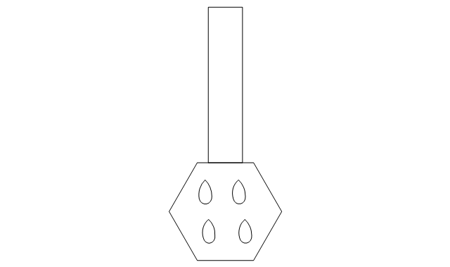
Electrical moisture sensor circuit symbol. In this project we will give you a design for a simple soil moisture sensor circuit that you can build on a breadboard. This article shows many of the frequently used electrical symbols for drawing electrical diagrams. Symbols of electronic sensors transducers detectors. This is very simple and interesting circuit for electronics lovers.
Symbols electrical symbology description proximity switch generic symbol switch by proximity to a magnet switch touch capacitive proximity sensor normally open outputt no capacitive proximity sensor 3 wire normally open outputt no capacitive proximity sensor 4 wire with 2 outputs one open and one closed symbols description. In this circuit we have used an npn transistor to detect soil moisture. In this project we are going to build a transistor based simple soil moisture detector circuit. In sensor circuits water sensor circuit with alarm if you are looking for a water level indicator or a water level controller there are pretty good circuits we have developed.
Electrical symbols electronic circuit symbols of schematic diagram resistor capacitor inductor relay switch wire ground diode led transistor power. The transducers sensors and electrical and electronic detectors are elements activated by the energy delivered by a system and that in turn deliver another type of energy to another different system the transformed energy may be of physical chemical or biological origin. The circuit will have two probes that you insert into soil. This soil moisture sensor circuit can be used in many applications like automatic plant irrigation system greenhouse projects etc.
Available in svg png jpg dxf dwg formats. It will turn on a small light called a light emitting diode led if the soil is too dry and the light will stay off if the soil is wet for a detailed explanation of how the circuit works see the help section. I already explained before that the schmitt trigger will suddenly change considerably at a certain point when the resistance is a certain value. This causes the circuit to change states.
Electrical symbols virtually represent the components of electrical and electronic circuits.


