Locus Diagram In Electrical Circuits Pdf

7 1 st el electrical diagrams a plot file in hpgl2 format is prepared and placed in a sub directory of the directory srv4 div drawings drawings elec hpgl.
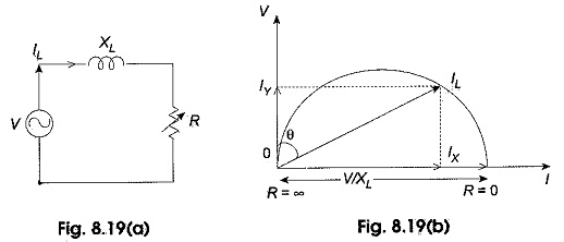
Locus diagram in electrical circuits pdf. Consider the locus diagram of rl series circuit with constant resistance r but variable reactance x l as shown in fig. Locus diagrams resonance. Locus diagrams series r l r c r l c and parallel combination with variation of various parameters resonance series parallel circuits concept of band width and q factor. Any physical system is represented by a transfer function in the form of we can find poles and zeros from g s.
The location of poles and zeros are crucial keeping view stability relative stability. Electric circuits pdf notes ec notes pdf. Magnetic circuit basic definition of mmf flux and reluctance. When x l 0.
The diagram symbols in table 1 are used by square d and where applicable conform to nema national electrical manufacturers a ssociation standards. I l assumes maximum value of v r and θ 0 the power factor of the circuit becomes unity. Electrical circuitscircuit concept r l c parameters voltage and current sources independent and dependent sources source transformation voltage current relationship for passive elements kirchhoff s laws network reduction techniques series parallel series parallel star to delta or delta to star transformation magnetic circuitsmagnetic circuits faraday s laws of electromagnetic. Resonance locus diagrams for various combination of r l and c.
Resonance concept of band width and quality factor. Disconnect circuit interrupter circuit breakers w thermal ol circuit breakers w magnetic ol limit switches foot switches pressure vacuum switches liquid level switches temperature actuated. Here is an easy to use circuit diagram software coming with ready made circuit diagram symbols that makes it easy for. Electrical diagrams are archived in cdd as hpgl plot files.
The one line diagram is similar to a block diagram except that electrical elements such as switches circuit breakers transformers and capacitors are shown by standardized schematic symbols. Figure 2 circuit drawing line diagram. Locus diagram is presentation of impedance l or c or r where the r is on the x axis and the l c are on the y axis and can be used in the presention admittance and using ohms lw we can get the current in a circuit or voltage on that circuit. Using easy software to make pdf circuit diagram create circuit diagram from ready made symbols and export to pdf with 1 click.
Faraday s laws of electromagnetic induction concept of self and mutual inductance. Analogy between electrical and magnetic circuits. As the value x l is increased from zero i l is reduced and finally where x l is α current becomes zero and θ will be lagging behind the voltage by 90 as. Native cad files of st cv diagrams are also stored in cdd.
The purpose is to help electrical engineers gain a detailed understanding of how the circuit works.


