Loop Power Indicator Circuit Diagram
Loop Powered Devices Selection Guide Engineering360
Hazardex The Use Of 4 20ma Indicators In Hazardous Areas
Fundamentals System Design And Setup For The 4 To 20 Ma Current Loop Ni

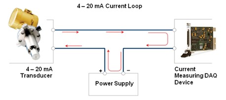
Current Loop Connection Divize Industrial Automation
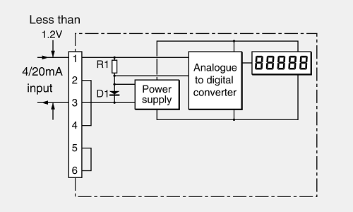
The Use Of 4 20ma Indicators In Hazardous Areas

Simple Car Battery Charger And Indicator Circuit Diagram Battery Charger Circuit Car Battery Charger Circuit Diagram
For this the indicator can be set as primary or secondary hart master and actively inquire the values from the sensor.
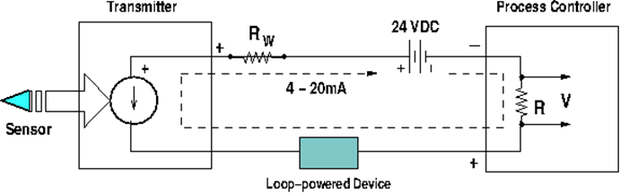
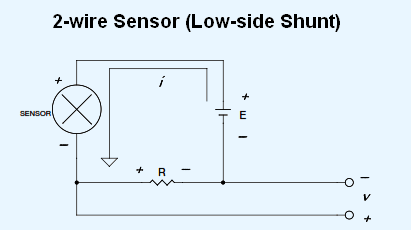
Loop power indicator circuit diagram. The wiring method of the external powered transmitter. 5 an indicator to show what the transmitter is measuring. 3 a transmitter to control the current through the circuit. 4 a sensor wired to the transmitter to detect the quantity being measured.
Wiring diagram of loop powered isolator with external powered 4 wire transmitter. Power was instead used in the loop the magnitude of current would be continuously changing making it difficult to discern the signal level being transmitted. Rosemount 751 series wiring diagrams a b c 3144p 751 a b c 2051 t 751 4 20 ma dc. A parallel configuration will allow the removal of the 751 indicator without affecting the integrity of the 4 20 ma loop.
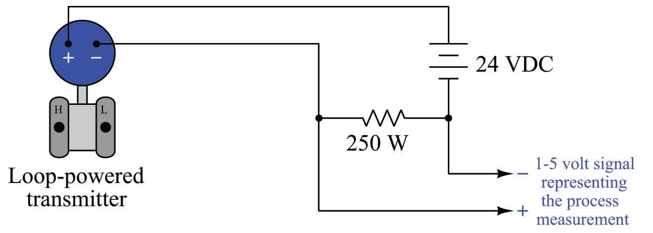
Additionally spare 751 indicators can be added without disrupting the loop. For 4 20ma current loops with 2 wire transmitters the most common loop power supply voltage is 24v dc but there are also instances. A switch loop single pole switches light dimmer and a few choices for wiring a outlet switch combo device. The indicator is designed so the analog or lcd display meter can be removed from the housing without impacting the integrity of the 4 20 ma loop.
Removal of the entire device from the series configuration will disrupt the loop. Rosemount 751 parallel wiring diagrams parallel wiring diagrams for rosemount 3144p temperature transmitter. 6 a controller to act on the measured signal. In the hart version up to 4 measured values of one sensor can be indicated in alternation.
Power supply indicator and controller are combined into one device. There are several different types. In electrical signalling an analog current loop is used where a device must be monitored or controlled remotely over a pair of conductors. Loop powered devices are often much lower cost than other process control devices with built in high power electronics.
The following is seven wiring diagrams of the loop powered signal isolator and the various powered sensors and the different types of control system input module or input of instrument. The process indicator is available with 4 to 20 ma or with hart protocol. Only one current level can be present at any time. A phase locked loop or phase lock loop pll is a control system that generates an output signal whose phase is related to the phase of an input signal.
Also included are wiring arrangements for multiple light fixtures controlled by one switch two switches on one box and a split receptacle controlled by two switches. A major application of current loops is the industry de facto standard 4 20 ma current loop for process control applications where they are extensively used to carry signals from process instrumentation.

True Bypass Looper Wiring Diagram Led Indicator 3pdt Switch Guitar Pedals Diy Guitar Pedal Guitar Diy

The Science Of 4 To 20 Ma Current Loops Application Note Bapi

Subwoofer Music Level Indicator Circuit Homemade Circuit Projects Electrical Projects Electronic Circuit Design Diy Amplifier
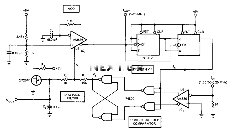
Full Band Phase Locked Loop Circuit Diagram Fast Under Pll Circuits 58822 Next Gr
How To Make 4 20 Ma Current Loop Measurements
The Hart Digital Analog Hybrid Standard Digital Data Acquisition And Networks In Control Systems Automation Textbook
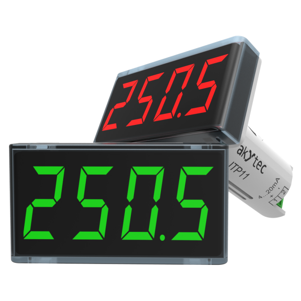
Itp11 Process Indicator 4 20 Ma Loop Powered Akytec

4 20 Ma Potentiometer Generator Divize Industrial Automation

Circuit Diagram For Power Failure Alarm Electronics Circuit Power Failure Alarm

Cn0267 Circuit Note Analog Devices
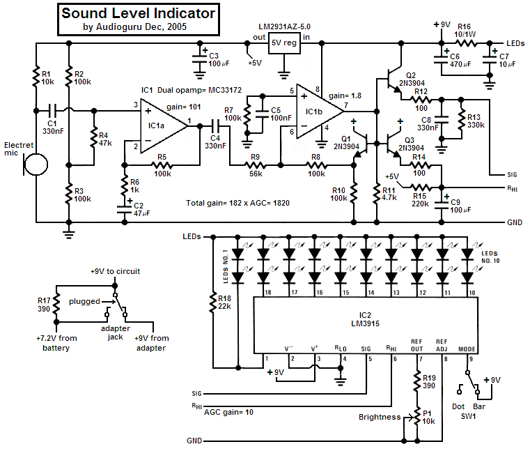
Sound Level Indicator Electronics Lab Com

Water Level Indicator Alarm Alarm Circuit Design Electronic Engineering
Mains Power Supply Failure Alarm Circuit Design

