Sf6 Circuit Breaker Control Circuit Diagram Pdf

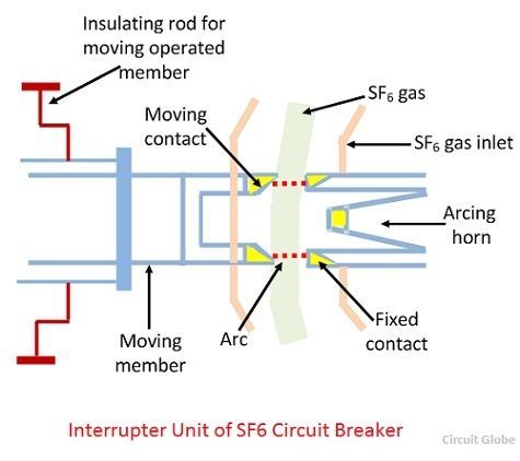
The sulphur hexafluoride gas sf6 is an electronegative gas and has a strong tendency to absorb free electrons.
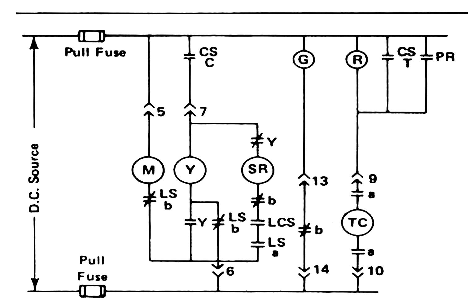
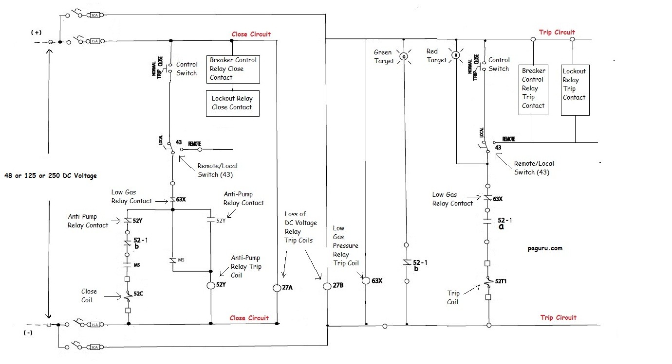
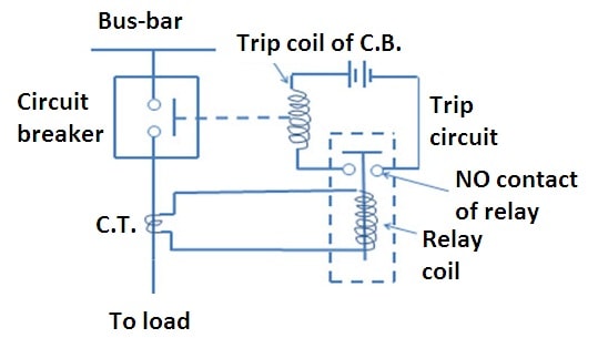
Sf6 circuit breaker control circuit diagram pdf. Circuit breaker box diagram. Cb main contacts not part of the control circuit releases the energy to move the main contacts open and close not part of the control circuit energy charging system. Circuit breaker control schematic explained a quick look at a typical medium voltage circuit breaker control scheme with an explanation of important components. Circuit breaker panel wiring diagram pdf.
During operation of sf6 circuit breaker this highly compressed gas is released through the arc in the breaker and collected to a relatively low pressure reservoir and then it is pumped back to the high pressure reservoir for reutilizing. Provide energy to the operating mechanism 4 9. All control components have been type tested for use on our circuit. Posts related to sf6 circuit breaker control circuit diagram.
555 timer circuit. Circuit breaker is of gis or dead tank type depending on the capacitance of the liaison to overhead lines it is considered as a gis or ais circuit breaker. In an sf6 circuit breaker sulphur hexafluoride gas is used as the arc quenching medium. Every control configuration of a circuit breaker can therefore be designed individually.
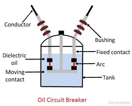
The contacts of the breaker are opened in a high pressure flow sulphur hexafluoride sf6 gas and an arc is struck between them. Air circuit breaker diagram. The circuit breaker poles contain sf6 at a pressure of 380 kpa for 36kv application and 550kpa for 40 5 kv application. Motor circuit breaker heating circuit breaker special features above and beyond these two standard variants a large number of further components and options are at our cus tomers disposal.
The working of sf6 circuit breaker is a little bit different in modern. Provide the means for supervision of the insulation and or arc extinguishing media solenoid devices energized a valid closing signal being received. In iec it is considered to be ais if the capacitance of the liaison between circuit breaker and a line is less than 1 2 nf. A typical wiring diagram with dc control for a westinghouse dhp is shown in the figure below.
By means of the special spring catches hook the ropes to the circuit breaker hook to the special anchoring points provided in the structure and lift. 555 timer circuit diagram pdf. 5w led driver circuit diagram. Update of sf6 primary distribution circuit breaker english pdf information technical commercial information hd4 low mid duty upgrade english pdf information technical commercial information new auxiliary contacts and electrical diagrams for hd4 series english italian pdf information hd4 gas insulated circuit breaker.
Earth leakage circuit breaker diagram. Sf1 circuit breaker 10 sfset circuit breaker 11 sf2 isf2 circuit breaker 12 auxiliaries 13 operating mechanisms and diagrams sf1 sfset circuit breaker 14 sf2 circuit breaker 16 protection and control monitoring protection units 18 vip13 protection unit 20 vip17 protection unit 21 vip200 vip201 control units 22 time current curves 25.
