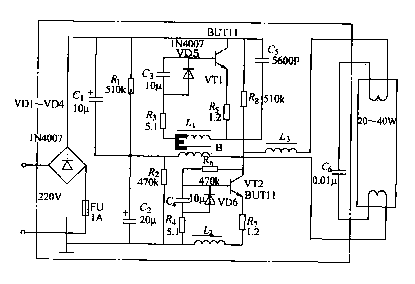
Simple 40w Electronic Ballast Circuit Diagram

Blocks any electromagnetic interference rectifier.
Simple 40w electronic ballast circuit diagram. See more ideas about circuit diagram electronics circuit circuit. Maintain a constant current when the lamp is operating in the steady state. A wiring diagram is a streamlined standard pictorial representation of an electric circuit. Assortment of fluorescent ballast wiring diagram.
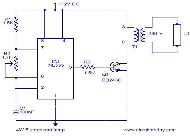
In present days electronic ballast design is so robust and somewhat complicated to work very smoothly with high leveled controlling ability. The vco pin sets the frequency of the half bridge gate driver outputs ho and lo pins. Here i have given the circuit diagram of electronic ballast with proper indication and explained each part of the circuit. It reveals the components of the circuit as streamlined forms and the power and also signal links in between the gadgets.
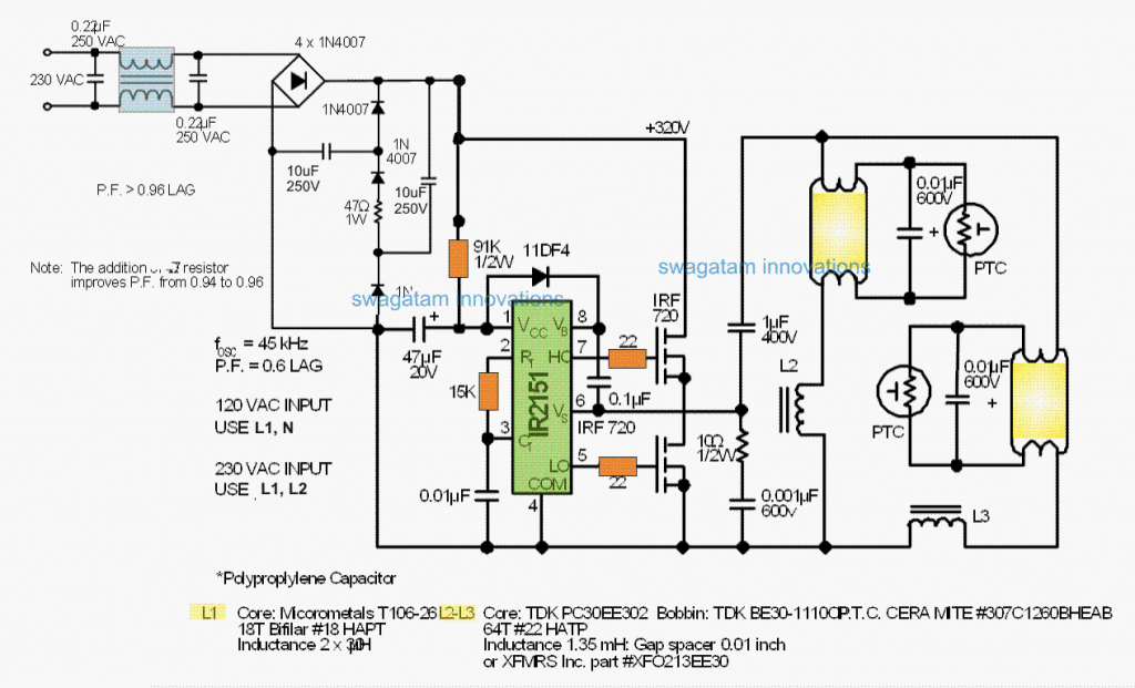
The next concept below explains how to build a simple yet extremely reliable electronic ballast circuit for driving or operating two 40 watt fluorescent tubes. Variety of 2 lamp t12 ballast wiring diagram. The circuit includes figure 5 the complete control for the half bridge resonant output stage and the lamp. It does power factor correction half bridge resonant output.
Electronic lamp ballast main purpose to generate the light out of a low pressure fluorescent lamp the electronic circuit must perform four main functions. Sep 16 2020 explore juni jones s board circuit diagram on pinterest. Electronic circuit schematics note that all these links are external and we cannot provide support on the circuits or offer any guarantees to their accuracy. A wiring diagram is a simplified standard photographic depiction of an electrical circuit.
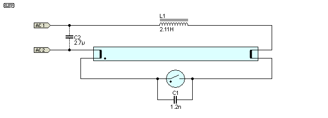
Here you also find the block diagram of electronic ballast which will help you too much to understand the electronic ballast circuit. Some circuits would be illegal to operate in most countries and others are dangerous to construct and should not be attempted by the inexperienced. Converts dc to square. Series vs parallel ballasts and wiring when a series ballast rapid start operates multiple lamps and one lamp fails the circuit is opened and the other lamps will not light.
Provide a start up voltage across the end electrodes of the lamp. The basic components used in the electronic ballast are listed below. Ballast design a 26w electronic ballast circuit without pfc is designed around the irs2526ds mini8 ballast control ic. Assure that the circuit will remain.
Twin 40 watt ballast circuit diagram. It reveals the components of the circuit as streamlined shapes and also the power and also signal connections between the devices. Electronic ballast circuit diagram with the explanation of the working principle.

