Simple Start Stop Jog Wiring Diagram

April 6 2019 april 12.
Simple start stop jog wiring diagram. Physical switches wired to outputs devices such as motor contactor. See image below for an example of 3 wire control being used to pull in a contactor to start a 3 phase motor. I zl ii i i ii i i fo 0. As long as you follow the ladder diagram and take it one wire at a time its simple.
Let s start with the basic stop stop circuit. Start stop switch wiring diagram start stop schematic start stop switch diagram appleton cf20b stop start wiring diagram onan generator start stop switch wiring start stop push button wiring diagram. Start stop wiring diagram sample wiring diagram for a start stop station. Here is what it looks like hard wired.
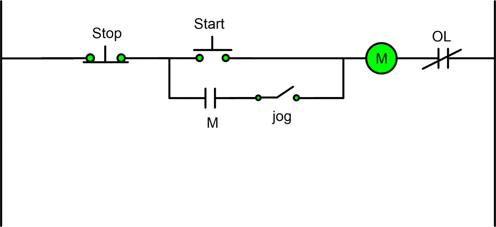
The jog circuit in configuration 1 operates as follows. When you press the start button and the stop button is not pressed the 24vdc relay energizes and it pulls in the r1 contactor that feeds three phase power to the motor. It reveals the components of the circuit as streamlined shapes as well as the power as well as signal links in between the gadgets. This video is a step by step explanation of wiring start stop basics.
Collection of start stop wiring diagram. Looking at a stop start jog circuit in the plc will help us in understanding the differences in hard wiring the circuit and programming. 3 phase contactor wiring diagram start stop. What is direct line starter its theory of starting circuit globe.
With the switch closed the control circuit acts as a normal stop start station controlling a load connected to the pilot device power is sitting on the start and seal. Wiring diagram for motor starter 1 phase motor starter wiring. Start stop and jog. Capacitor start capacitor run motor wiring diagram.
Typical wiring diagrams for pushbutton control stations start stop control wiring diagrams single station basic circuit r 1 kla i. Motor control jog circuit diagram. Start stop jog circuit motor control circuit diagram. I operation depressing the start button energizes coil m hold in contacts m and maintains the circuit after the start button is released.
The most common use of 3 wire control is a start stop control. A wiring diagram is a streamlined conventional photographic representation of an electric circuit. A switch is wired in series with the seal in of the pilot device.


