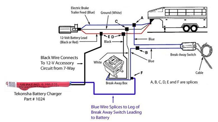
Trailer Breakaway Wiring Schematic

This car is designed not just to travel one place to another but also to take heavy loads.
Trailer breakaway wiring schematic. These 2 wire diagrams fit the needs of most trailers. Use only the needed wires and ignore the others. This guide will be discussing trailer breakaway box wiring. A wiring diagram is a streamlined conventional pictorial representation of an electric circuit.
As the name implies they use four wires to carry out the vital lighting functions. This automobile is designed not just to travel one place to another but also to carry heavy loads. The four wires control the turn signals brake lights and taillights or running lights. 4 way trailer connectors are.
Assortment of electric trailer brake wiring schematic. Trailer breakaway wiring diagram 3 wire trailer breakaway switch wiring diagram hopkins trailer breakaway wiring diagram rv trailer breakaway switch wiring diagram people today understand that trailer is a vehicle comprised of quite complicated mechanics. 4 way trailer connectors are typically used on small trailers such as boat snowmobile utility and other trailers that that do not use brakes. Typical trailer wiring diagram and schematic.
It shows the components of the circuit as streamlined shapes and the power and also signal connections in between the devices. Only the blue brake and white ground wires are different. A wiring diagram is a simplified conventional photographic depiction of an electric circuit. Expand the same for additional axles.
They also provide a wire for a ground connection. Trailer breakaway box wiring diagram trailer brake battery box wiring diagram trailer brake box wiring diagram trailer breakaway box wiring diagram folks understand that trailer is a vehicle comprised of very complicated mechanics.


